Conduit and Raceways
- Apr 12, 2022
- 5 min read
Updated: May 16, 2022
General - The 2020 edition of the National Electrical Code outlines the requirements for raceways, channels for routing conductors and cables, in Chapter 3. General requirements are provided in Article 300 and more specific requirements are provided throughout the remainder of Chapter 3 for various raceways, including conduits, cable trays, messenger wire systems, and more. Raceways get wiring from point A to point B while ensuring safety and functionality in the design.

Metal Conduit Routing Conductors Between Pull Locations
Conduit is the most common form of raceway. If you go look around your house, outside at power poles, or in many public spaces, you will find some form of conduit being used to route electrical power safely. Some of the most common types of conduit used for construction are Electrical Metallic Tubing (EMT) and Polyvinyl Chloride (PVC). Both conduits can be used in similar applications, which is why you'll see them all over the place. Other conduit types, like Rigid Metal Conduit (RMC), High-Density Polyethylene (HDPE), and several others, are also used but generally in specialty applications where the conduits' particular properties are relevant.
Conduit is provided in standard trade sizes generally varying from 1/2" to 6". These trade sizes are just the inside diameter of the conduit being used. Outer Diameters of conduit will vary based on the type used. Thicker conduits are used when additional physical protection is required, as outlined in NEC Article 300. Conduit is usually sold in 10' sticks. There's a good chance your local home repair store will have 10' sticks of more basic conduit types available.
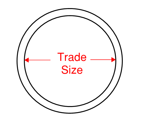
Diagram of Conduit Diameter as the Trade Size
Cable trays (covered in Article 392) and messenger wire systems (covered in Article 396) are two other commonly used types of raceways, although generally for commercial and industrial applications, not residential. Cable tray has special fill requirements that may lead to ampacity modifications depending on the amount of conductors, the spacing between them, and so on. This means that conductors installed in cable tray, even when installed close to one another, may not be subject to the same derating factors of NEC Article 310. Messenger wire systems have a much more limited section than cable tray, but they also see an ampacity shift. Conductors routed in a messenger wire system have a unique ampacity table for low voltage applications, NEC Table 310.20. In either case, when a conduit isn't totally enclosing conductors, an improved ampacity may be available. This is why systems like cable tray and messenger wires are often used in large, engineered facilities.
Conduit Fill - The number of conductors that are installed inside of a conduit is limited by more than the bundling derating factors for ampacity. Additionally, designers need to consider the size of the conductors relative to the size of the conduit. Placing too many conductors inside of a conduit can lead to challenging installation conditions, and, consequently, an increased chance of damaging the conductors. Conduit fill limitations are prescribed by the NEC to prevent these situations from happening.
NEC Chapter 9 Table 1 provides the basis for these conduit fill requirements:
For 1 conductor/cable, the conduit can be filled to no more than 53% of its cross-sectional area
For 2 conductors/cables, the conduit can be filled to no more than 31% of its cross-sectional area
For 3 or more conductors/cables, the conduit can be filled to no more than 40% of its cross-sectional area
The vast majority of applications utilize either a single cable (think 2 or 3 conductors with a ground in a single assembly) or multiple conductors. For this reason, most people just remember conduit fill as "the 40% rule". Note that when two cables are pulled the allowable conduit fill is actually lower than 40%.
NEC Chapter 9 has a lot of additional information regarding conduit fill, including how many low voltage conductors of standard types can be pulled through conduits of standard sizes. Calculations are required for medium voltage installations, as conductor sizes can vary considerably.
Conduit Bending - Fill isn't the only problem that we have to consider when designing conduit. Conductors are also limited to safe bending radii. If a cable is bent at a radius which is too tight, the cable itself can be damaged. This could be the insulation, the shield (for medium voltage), the jacket, or all of it. Bending radius requirements are provided in NEC Article 300. The minimum bending radius for shielded cable is 12 times the conductor diameter. Unshielded cable can be installed with a radius of no more than 8 times the conductor diameter. Conduits can usually be purchased with prefabricated elbow connectors that are already bent to a radius suitable for conductors.
Between any two pull points, conduit is not permitted to bend more than 360 degrees. This rule is found under each of the various conduit Articles throughout Chapter 3. There is no limit on the number of turns required, so (4) 90 degree turns could be used, (8) 45 degree turns could be used, or any other combination.
Jamming - The last recommendation for proper conduit sizing is to minimize the possibility of jamming. Jamming is only a significant concern when pulling exactly three conductors through a conduit, provided the conduit fill requirements above have been met. Jamming is caused by the tendency of three conductors to level out as they're pulled around bends. The jamming ratio, J, is defined as:
J = d / D
Where:
J is the jamming ratio, a unitless metric used to determine when jamming is probable
d is the inside diameter of the raceway (the trade size) in inches
D is the diameter of a single conductor pulled through the raceway in inches
If the jamming ratio, J, is between 2.8 and 3.2, and three conductors are being pulled simultaneously, jamming is more likely to occur. Conduits should be changed in size, where possible, to mitigate the potential for jamming.
Example: Determine the appropriate conduit size and bending radius for (3) XHHW-2 500 KCMIL Copper conductors.

Solution: Begin by determining the acceptable conduit fill. The area and diameter of XHHW-2 500KCMIL conductors can be found in NEC Chapter 9 Table 5. The area of each conductors is .6894 in^2 and the diameter is .943 in.
Next, determine the required conduit area. For 3 or more conductors, the conductors can fill no more than 40% of the conduit's interior cross-sectional area. This means that the conduit must have sufficient area, a, as follows:
a = (.6894 in^2 * 3) / .4 = 5.1705 in^2
This area can be converted into an equivalent conduit interior diameter (trade size), d, using circular geometry:
d = 2 √( a / π ) = 2 √( 5.1705 / π ) = 2.566 in
This means that a conduit with a minimum diameter of 2.566 in is required. The next standard trade size can be found from NEC Table 300.1. 3 in conduit is the next size up and should be used. Depending on the exact dimensions of the conduit, a 2.5 in conduit may be suitable.
Where bends occur, conduit must have sufficient radius to protect the conductors from damage during pulling. XHHW-2 conductors are unshielded, so they require a minimum bending radius of at least 8 times the conductor diameter. This equates to 7.544 in for the conduit bending radius.
Since three conductors will be pulled through simultaneously, jamming must be verified. The jam ratio, J, can be computed:
J = 3 / .943 = 3.181
Since the jamming ratio is less than 3.2 and greater than 2.8, jamming may occur. Upsizing the conduit to 3.5 in, the new jamming ratio is:
J = 3.5 / .943 = 3.71
With a 3.5 in conduit, jamming should not occur. For this reason, a 3.5 in conduit is recommended for installation of (3) XHHW-2 500 KCMIL conductors installed at the same time.


